Tuesday, December 17, 2013

Printing glass environments without support material on the Afinia H-Series

Afinia H-Series 3D Printer Setup
After installation of the Afinia Software, turn on the printer via switch from the back. In order to ensure that the design prints properly on the slide, the build plate must be leveled correctly. Access to changing nozzle height branches from clicking on the menu bar 3D print>Maintenance. In the following screen, the option for changing the height for each of the corners can be accomplished by selecting each of the options of “FL, FR, Center, NL, NR” and selecting set nozzle height to a particular height by clicking on “Set Nozzle Height>Yes.” This can be accomplished successfully by setting the nozzle height in the center and each corner of the build plate at a displacement exactly 2 mm between slide and nozzle. In regards to appropriate extruding of the ABS plastic, the displacement between the slide and nozzle must be exactly 0.2 mm. Once proper leveling has been established, printing of the selected environment for the slide can be proceeded to.

Printing with the Afinia H-Series 3D Printer
Before printing, it is imperative to become acquainted with the functions of the printer so that each step of the print can be recognized from the printer itself (Figure 5).
Figure 5. Table of Status Indicators for the Afinia H-Series 3D Printer.


Initialize the Afinia by clicking from the menu bar 3D print>Initialize.  Once initialized, begin heating the table via menu bar 3D print>Maintenance>Table Heat 1 HR. Heating the table to the optimal temperature of ~105° C will take 15 minutes, and another 10 minutes to ensure that the plastic will extrude solidly. It is important to begin this process before following the steps that ensue, for this will allow for the desired environment to print as fast and nicely as possible.
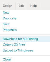
After the table begins to heat, select the design you wish to print from Tinkercad by selecting the option from the menu bar File>Download for 3D Printing. This will prompt for selection of a format to print the design; create the file as an STL or UP3. In the Afinia H-Series Software, select Auto-Placement of the file and the fix option to ensure that the environment printing on the slide is appropriately centered and contains no errors that will cause any deformations in the environment. The auto-placement option can be selected from the menu bar File>Auto-placement, and the fix option can be selected from the menu bar Edit>Fix. With the design auto-placed and fixed correctly, it is time to set the design at the right level on the platform to print on. Since the design will print without a base or support material, the design must be leveled exactly on the slide. To do so, click on the design within the software and pay close attention to the “Min” settings. Select from the menu bar Move, and once highlighted, select “-1” in the scroll bar and move down the object to exactly 0 mm in the z-direction. Next check the printing settings by clicking the menu bar 3D Print>Setup or the 3D print>Preferences from the button. The only settings that need to be manipulated for the design is printing with the “only base” option and the solid fill settings. Printing without support material and with a solid filling is imperative for maximum clarity of the worm and for strength and stability of the design. After the printer has been heating up for approximately 10 minutes after the build table has reached a heat of approximately 105° C, the design will be ready to print. This setup will work well for more simplistic environments, such as creating channels.
However, for the designs with posts, ensuring sturdiness of the posts for the print along with minimizing the amount of spewed plastic can be difficult. For these designs, it is recommended to not bring the design to print exactly on the platform by bringing it down in -1 mm increments from the z-axis. Instead, leave the design where it will be auto-placed and print with a base for the posts that is smaller than the printer can handle. This will allow for the printer to recognize that a base is in the design, yet since it can’t print the base it will treat the posts accordingly (Figure 6).
Figure 6. Glass slide smoothed with acetone-based glue and printed with standard Auto-placement settings.


Thursday, December 12, 2013

From Paper to Print to Production

     Here at JMU we have the ability to see many of our creative designs through to the end. We can go from just an idea in our heads to an actual finished product. As an example I designed a large AN-Fitting. I was able to mock up a design in solidworks:
    After the Design was finished it was off to the Mathematics Maker Lab were prototype prints were created:

     The Prototype looked good, and it was time to take this concept to the final stage. One of JMU's best keep secrets is the machine shop, it is a fantastic resource. Since I also work there I was able to machine my own part.

     Here is the raw aluminium stock used:

   A quick look at the part mid way through production:

     And a look at the finished part:

     
From start to finish, everything was done right here on campus!


Tuesday, December 3, 2013

Designing a Pencil Holder

My first project in openSCAD was design this Pencil Holder just to really learn the properties of openSCAD and some of the functions that are available to use such as the rotate_extrude and linear_extrude.


 I used several different shapes such as circles and squares for the all the structure. I also developed a cup like structure with the same design as the pencil holder in which I add a hollowed out cylinder using the difference function along with to handle piece on both side. I have not printed this design out yet. My sources were http://www.youtube.com/watch?v=ZUoBw1WR1S0 and http://www.youtube.com/watch?v=22iaz5xDzlM.

At the moment, I am working on another project in openSCAD, and have been playing with a Xbox Kinect to model real life objects, and if any one has few ideas or projects that can been done in openSCAD, I would be greatly interest in trying to do them. I can print your on --------> http://www.thingiverse.com/thing:195582

Monday, December 2, 2013

Adding Thickness to your STL file

This post will give a quick instruction on how you can add thickness to your 3D file by using Blender.
If you don't already have Blender, you can download it HERE.

Step 1. Import your STL file

            File -> Import -> Stl (.stl)

Step 2. Click on Modifiers -> Add Modifier -> Solidify


Step 3. Experiment with the settings in order to obtain a satisfactory thickness. For this model, I changed the Thickness to 2.0, Offset to 0, and checked that I wanted 'High Quality No' thus obtaining:


By adding thickness to certain models, it will make thin objects less brittle during a print, thus increasing the probability of achieving a successful print. :)

Phone Stand made in OpenSCAD

So, I had a little free time over Thanksgiving and ended up making this phone stand looking thing. I played around with openSCAD after developing a fancy pencil hold that I made in openSCAD on November 18, 2013 thanks to the tutorials done by Patrick Conner on YouTube


I used several different functions in openSCAD such as rotate_extrude, linear_extrude, and minkowski functions to get the different shapes in the picture above. I found a great function in openSCAD: $fn= input, which allows the user to put in a greater resolution for any particular shape. The higher input value the user puts in the object appears smoother.

To make your own I have the STL file right here: http://www.thingiverse.com/thing:194587

Monday, November 11, 2013

Exporting an STL from Matlab

In this tutorial, you will learn a simple way to export a 3D image as an STL by using Matlab. The functions you'll need to make the STL file in Matlab can be found in the 1st and 2nd link below, while a more in depth tutorial can be found in the 3rd link.

LINKS:

Okay: so let's get to it.

1. Save the above two functions into Matlab.

2. Make a 3D surface plot in Matlab.
For example, type in:
    >>  [X,Y] = meshgrid(-8,0.1:8); 
    >>  R = sqrt(X.^2+Y.^2) + eps;
    >>  Z = sin(R)./R;                  
    >>  surf(X,Y,Z)                      

3. Use the surf2solid function which you downloaded earlier:
    >> VariableName = surf2solid(X,Y,Z);

4. Use the stlwrite function that you downloaded:
    >> stlwrite('FileName.stl',VariableName)  
*FileName is to be replaced with what you want to name your file

And there you have it, a nice simple way of exporting a 3D file from Matlab. 

Wednesday, October 23, 2013

CubeX Trio vs. Afinia H-Series

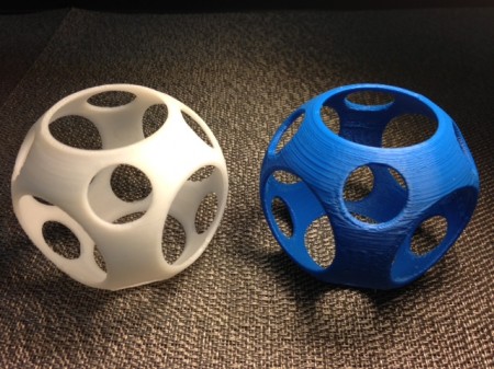
Today we pitted the giant CubeX Trio from the JMU MakerLab against one of our Afinia H-Series 3D printers. The Afinia won hands-down, but the chips were stacked a bit in its favor. First, the picture: The Afinia printed the beautiful white model on the left, while the CubeX Trio made the blue model on the right.
photo (1)
This model is the outermost layer of bytec's Five concentric balls model on Thingiverse. This was the very first print from our CubeX Trio, and we used the default settings it started with. We tried to match those same settings on the Afinia - .25mm and "normal".
Time winner:  Afinia.
The Afinia took about 45 minutes to print this model and the CubeX Trio took nearly three times as long - 2 hours and 45 minutes. What? We had heard the CubeX was notoriously slow, but this is ridiculous. There must be a way we can fiddle with the settings to improve this time.
Looks winner: Afinia, but at an advantage.
The Afinia had an unfair advantage here, printing in white ABS - which is so matte that you can hardly see the layers. The CubeX printed in a dark PLA, which is about the worst combination for light bouncing off the layers and making them obvious. Worse, the CubeX nozzle was clearly too close to the platform. This both is and isn't our fault - the CubeX calibration instructions were to set the nozzle/platform distance based on the first extruder head, and the blue came out of our third extruder head. Perhaps there is a way to calibrate this better... there must be! Again, remember this is our first print on the CubeX so we may find a way to improve this.
Smell winner: Afinia.
The smell of ABS filament while printing isn't the best, especially compared with the sweet maple-syrup/corn smell we are used to from the JMU MakerLab's Makerbot Replicator 2. But the CubeX's PLA smell is worse than ABS for some reason.
Noise winner: Afinia.
We had heard the CubeX Trio was quiet, and maybe it is when printing different models. But for this model, which had a lot of disconnected paths, the CubeX was quite noisy. Our Afinia handled this model with far less noise, although we know the Afinia can be noisy in other situations so it may not win this battle every time.
Software winner: Afinia.
It is difficult to express how clunky and difficult the CubeX software is while still being nice. A simple example: We can't figure out how to use the CubeX software to align a set of STL models that are colored separately.  We can import them and color them but then not align - something that is vital if we want to print a multicolored concentric balls model. The Afinia's software could stand a lot of improvement but it is our new best friend compared with what we went through setting up and using the CubeX.
Cost winner: Afinia.
The CubeX uses filament from a proprietary cartridge that results in a much higher cost. This is simply not acceptable.
Color/size winner, eventually: CubeX Trio.
To be fair, the point of the CubeX Trio isn't to be quieter, sweeter-smelling, cheaper, or faster than the Afinias or the Replicator 2.  The point is to print in up to three colors, with both PLA and ABS, and to be able to make HUGE models. We expect to be able to do this successfully fairly soon, and we expect that we will eventually love the CubeX Trio for its good point, despite its weaknesses and our apparently slow learning curve getting used to using it and its software. Stay tuned for a future post where the CubeX gets to show off its strengths instead of get beat up by a printer a quarter of its size and less than half its cost.

Trefoil Knot


We printed eduardoviruena's model of Escher's 3-knot, also called a trefoil knot, on Thingiverse.
The trefoil knot is essential to the study of knot theory and geometry.

This was printed on the Afinia with a fast quality at 0.3mm resolution.

Monday, October 21, 2013

Heatwave Vase

I went on Thingiverse over the summer and found a neat little design of a vase (http://www.thingiverse.com/thing:126567). The vase is called "Heatwave" according to the user. This seemed like a nice little decoration to have to put stuff in, and brighten the living space.

The vase's wall width is about 2mm thick, so the filling used here was "Solid", figuring that anything more might create unnecessary holes or gaps in the wall. The quality of this print was set at Fine, since we were dealing with such a small thickness.

Under the 'Part' section of the settings before printing, I chose to have the angle for the support material to be less than 10 degrees. This caused no support to be made.
The Surface, I left to be 3 layers.

Under the 'Support' Section on the same window, I choose to have 4 layers instead of 3 for the Dense section, with an angle of less than 10 Degrees also.
I left the Space to be 4 lines and the Area greater than 3 mm^2.

Smoothing your 3D models

There may be times where you wish to have a 3D model that you are printing be as smooth as you can possibly get it. For us, this happened when we wanted to take a non-spherical object that has a property where, when laid on the ground, always has the same width from the ground to the top such as the model being used in this tutorial.

Software you'll need:
      I. Blender http://www.blender.org/download

1. Open Blender and import your STL file.

2. Go from Object Mode to Edit Mode


Monday, October 7, 2013

The CubeX Trio is here!

Three extruder heads, ABS/PLA capability, and a print volume the size of a basketball!  The CubeX Trio is here and set up in the JMU 3-SPACE classroom in Burruss Hall.  The machine is in 3-SPACE only because is too big to fit in the MakerLab.  The CubeX belongs to the JMU MakerLab in Math/Stat so let us know if you have ideas for big math things to print!


For a gentle introduction to using the machine and its software look at the Beginner's Tutorial from Drexel Autonomous Systems Lab, and for leveling/hardware issues check out the CubeX User Guide.


It's a small pumpkin in there for size comparison, but still!

Saturday, October 5, 2013

Adding a Voronoi Effect to Your Model

In this post, you will learn how to Voronoi any mesh using steps that I found from this video:
                                                           http://vimeo.com/20150133

Things you'll want to download for this tutorial:

      i. Blender (http://www.blender.org/download)
      ii. Meshlab (http://sourceforge.net/projects/meshlab/files/meshlab/MeshLab%20v1.3.2/)

1.  Import your stl into Meshlab.

(Note: Meshlab lets you import other files than stl's, however stl is the format that I personally prefer to work with.)

2. Look at the number of faces your and vertices your object has. This can be found at the bottom of your Meshlab window.


These values seem to produce an adequate effect for what I have hoped to achieve in the past. If you have run this tutorial and you have problems, or it's not coming out as nice as you'd like, you may have too few faces. To solve this, open up Blender.

1. Import your stl

2. Change from Object Mode to Edit Mode

3. Hit 'A' On your keyboard to deselect everything, then hit 'B' to select the vertices of the faces you wish to subdivide. look in your mesh tools menu (on the left) and click subdivide. After getting a fairly equal subdivision across the surface of your mesh, you are ready to move on to working with Meshlab.

Wednesday, September 25, 2013

Machines Building Machines

Machines Building Machines


While the take over of Skynet and the extermination of the human race by machines may be several years down the road still, it seems John Conner's warnings went unheeded as we head toward a brave new world where our 3D printers can create parts for more 3D printers! As seen here, we were able to print replacement parts (Kudos to Lawsy for the file) on the Makerbot for a Solidoodle printer.

replacement parts

With just a little over 3 hours in print time with .1mm layer height, we in the JMU math lab were able to create working replacement parts to fix the Solidoodle feeding mechanism. 

replacement parts installed
Above is a close look at the new and improved, 3D printed, feeding mechanism on the Solidoodle.

Friday, July 12, 2013

Removing support material

TIP-When removing support material, it is best to go in the direction perpendicular to the lines facing the plastic as shown.


Makerware log file location

If makerware ever tells you to check its log, they are saved to:
/Users/6dlab/Things/Logs
A new log is created every time the program is started so if you are trying to isolate an error, quit the program, start again and then try to reproduce the error.

Monday, July 1, 2013

What to do if the Afinia print head jams

First see if there is any extra material that can be removed from the print head (threads). If removing these does not fix the problem, Fletcher Grow in the engineering department has another solution:
If when loading the ABS filament you hear a clicking noise, you can fix the problem by taking off the extruding head and soaking it in acetone for about 20 minutes. After that wash off the head.

Friday, June 28, 2013

Fixing error "material isn't enough, please replace new spool" and Do you have enough material for afinia?

This blog post will explain how to ensure that you have enough material left to print a model given a certain weight. If you get the error below this blog post will also be helpful.
If you are trying to eliminate the error above and you are sure you have enough material left, the fix is simple. Simply go to 3D print>Maintenance from the Afinia software, then click the new spool button. Set the material type you are using and the weight to 700 g and click OK. This will reset the program's internal counter of material used.
If you would like to know if the material you have is going to be enough to print a model you can weigh it on the black scale in the lab and then enter this weight into the new spool dialogue box instead. If you are also weighing the spool, an empty spool weights about 280 grams so simply subtract this from your measurement. The stand for the spool weighs about 52.3 g so this can also be subtracted or the scale can be tared before placing the spool onto it.

TIP: there is also a 500 g calibration weight that can be used if the scale needs to be re-calibrated. Follow the instructions on the cover of the scale to tare and re-calibrate.


How to clean sand paper

The plastic can be removed easily from the sand paper in the lab by lightly wiping it with a paper towel.

What to do if the max nozzle height isn't high enough

If are trying to set the nozzle height and the printer's max height isn't allowing the build plate to come up high enough simply type the maximum value into the 'to' field and click set nozzle height. Once this new height is set, the program then increases the max up by another mm. You can repeat this until you get the height you need.


Wednesday, June 19, 2013

What to do if the Afinia print button doesn't work

The print button

If you try to click on the print button from the Afinia software (mac version 1.4 (3.1)) and nothing happens then follow these steps to re-install.


  1. Drag afinia application to trash folder from the applications folder
  2. Delete the file: users/6dlab/Library/Preferences/AfiniaMicroboards.Afinia.plist
  3. Empty trash
  4. Restart mac
  5. Re-install Afinia software from either the google drive location, the interent, or the install CD in the lab

Note-the google drive folder that is referenced is:
6dlab/3-D Team/software install packages/
If you are on a different computer, replace "6dlab" with your own user name.

This might also solve other problems you may be having with the software but it has been verified that this procedure fixes this problem.

reference:http://www.cultofmac.com/90060/how-to-completely-uninstall-software-under-mac-os-x-macrx/

Tuesday, June 18, 2013

Volume by Shells and Disks


3D: Volume by Shells and Disks


The goal of this project is to teach students how to create a 3D visualizations of volume by shells and disks for any mathematical function using the following two programs:


Things that you'll need to do before starting to design:


  • Determine which function you wish to work with
  • Determine radius and heigh of each shell/disk
  • Determine how large you want the object to be

So for our example, our team used the following conditions:

  1. The function used: f(x) = -x^2-x+8 rotated around the y-axis for the x range from 0-2. 
  2. There were four disks and four shells made for this visualization of approximating volume, and with some simple mathematics and some help from the quadratic formula, we were able to determine the radius and heigh of each of the disks and shells.
  3. For the print, the radius of each object was scaled up by 14mm and the height was scaled by 5mm.

Now, let's move on to how the parts were actually modeled.

Towers of Hinoi

The base for the popular puzzle 'Towers of Hinoi' is being used since it can lay out the three models in a way that would easily convey the idea that the volumes were similar.

To make the Tower of Hinoi, we used Tinkercad, which can be accessed here: https://tinkercad.com/
  1. The first step for making the towers is to create the rectangular base. To do this, go into tinkercad and select the box tool and place it down upon the workplane. 
  2. Select the ruler tool and place it down upon the workplane. This allows you to type in the desired dimensions of the object. (We picked a rectangle with dimensions140x70x4mm)
  3. Select the Workplane tool and place it on top of your rectangle. Doing this will allow you to smoothly place one object onto another.
  4. Place the ruler on the corner of the rectangle so that the coordinates of the rectangle as compared to the origin of the ruler are (0,0).
  5. Choose the Cone tool and place it upon the workplane. We gave the cone a diameter of 12mm and a height of 4.28mm. Copy the cone and paste it twice, thus creating two new cones.
  6. We wanted to place the cone at coordinates (35,35), (105,35), and (175,35). Since the object has a radius of 6mm, we had to place the cones at (29,29), (99,29), (169,29) in order to get the center of the object to the desired coordinates. 
  7. Next, choose the Cylinder tool.  We gave the cylinder a diameter of 6 and a height of 35.71
  8. Now position these cylinders on the platform at (32,32), (102,32), (172,32).
  9. Now select all of the shapes and click on the group tool at the top right. Now you are done!
  10. At the top right, click design and scroll down to 'Download for 3D printing.' Say you want it as an STL and you'll now have your 3D model available to be imported into other 3D software!


Now that you have a basic understanding of how the design is made, try tinkering the rest of these basic shapes yourself! You'll want to make the hols slightly wider so that when everything is 3d printed, they will fit together nicely! (We would tell you how much wider the holes would be, but it appears the additional layer thickness that the machine produces varies depending on what model you have) If you still are lost, follow some of the tutorials on the tinkercad website under LEARN. Also, don't forget to add the hole in your design for the cone at the bottom of the tower.


OH! One more note.
To make the actual function, we typed the following into Mathematica:
RevolutionPlot3D[function,{x,0,2}]
Export["Name of file.stl",%]

GrabCAD


In searching for sites that contained a large number of STL files, I stumbled across GrabCAD. This site contains over 80,000 STL files. (Most of the files on this site are engineering based, but there exists a handful of mathematical objects such as knots, fractals, and klein bottles). It also has a program that may come in useful at some point called GrabCAD. GrabCAD theoretically is beneficial for getting external input on your 3D model. However, upon further inspection, it may be no more effective than plugging a 3D file into a shared Google Drive folder.

All the same, go check it out! You might find something awesome.